Pages

Selasa, 18 Oktober 2011

NetworkTrafficView alat Pantau Lalu Lintas Jaringan

NetworkTrafficView adalah aplikasi freeware dari Nirsoft yang memungkinkan pengguna untuk memantau lalu lintas jaringan. Ini adalah alat monitor jaringan yang menangkap paket melalui adaptor jaringan anda, dan menampilkan statistik umum tentang lalu lintas jaringan. NetworkTrafficView bisa membantu untuk mengetahui semua lalu lintas jaringan dan memeriksa apakah ada malwares atau spywares transmisi informasi ke internet. Aplikasi ini didukung pada semua versi Windows, mulai dari Windows 2000 dan sampai ke Windows 7, termasuk 64-bit.
properties NetworkTrafficView alat Pantau Lalu Lintas JaringanStatistik paket dikelompokkan oleh Jenis Ethernet, IP Protokol, Source / Tujuan Alamat, dan Sumber / Tujuan port. Untuk setiap baris statistik, informasi berikut ini tampilan: Ethernet Type (IPv4, IPv6, ARP), IP Protokol (TCP, UDP, ICMP), Alamat Sumber, Tujuan Alamat, port sumber, port tujuan, Name Service (http, ftp, dan sebagainya), paket Hitung, Jumlah paket Ukuran, Jumlah data Ukuran, Speed ??Data, maksimum Speed ??Data, Ukuran paket rata-rata, Pertama / Waktu paket terakhir, Durasi, dan proses ID / Nama (Untuk koneksi TCP).
Anda mungkin perlu memilih adaptor jaringan untuk memonitor lalu lintas, pastikan anda menjalankan alat dalam modus administrator untuk mendapatkan rincian.
NetworkTrafficView merupakan aplikasi portabel dan tidak memerlukan instalasi. Anda dapat menekan F6 untuk menghentikan aktivitas monitor lalu lintas jaringan, F5 untuk memulai lagi, atau Ctrl + X untuk menghapus statistik jaringan lalu lintas saat ini.

Sabtu, 15 Oktober 2011

Menyiapkan perbaikan periphera


        Pepiperal computer merupakan peralatan pendukung computer dari sebuah PC terkadang peripheral tersebut bekerja sebagai mana fungsinya atau rusak untuk di lakukan perbaikan pada peripheral tersebut.
Sebelum melakukan perbaikan perlu disusun langkah-langkah persiapan perbaikan sebagai berikut:
Ø Mempersiapkan alat-alat bantu yang gunakan perbaikan.
Ø Mendiagnosa kerusakan-kerusakan yang terjadi.
Ø Menemukan bagaimana cara melakukan perbaikan periperal tersebut.
Melakukan perbaikan
Sedangkan melakukan perbaikan peripheral di butuhkan beberapa alat bantu atau tools liat sebagai berikut:
·        Obeng
·        Tang
·        Kuas
·        Kain kering atau tisu dan kain pembersih
·        Penyedot debu mini/vocum cliner
Peralatan yang di butuhkan untuk melakukan perbaikan peripheral:

a.     Obeng
Obeng merupakan alat yang paling penting dalam melakukan perbaikan peripheral obeng berguna sebagai. Untuk membongkar dan memasang peripheral,untuk selanjutnya di lakukan perbaikan.obeng ada bermacam-macam bentuknya,mulai dari obeng (+),obeng(-) serta obeng bintang/kembang.untuk melakukanperbaikan peripheral perlu disiapkan obeng dari berbagai ukuran.
b.     Tang
Untuk melakukan perbaikan peripheral digunakan tang cucut. Kombinasi tang cucut banyak di gunakan untuk memegang kepala sekrup atau jumper yang kecil.
c.      Kuas
Kuas digunakan untuk membersihkan komponen peripheral dari debu dan kotoran-kotoran yang menyebabkan karna masalah kotoran seringkali menjadi penyebab peripheral tidak dapat berfungsi lagi dengan baik.
d.     Penyedot debu mini/vocum cliner

Penyedot debu mini berfungsi hamper sama dengan kuas, yaitu untuk menghilangkan kotoraan yang menempel pada peripheral. pada ujung penyedot debu mini di lengkapi dengan sikat, dengan ukuran yang beragam di maksudkan untuk di sesuaikan luaas sempitnya sudut-sudut pada peripheral.alat ini sangat tepat digunakan untuk membersihka kotoran yang terdapat pada keyboard pentilasi udara pada monitor dan pada fan.
e.      Kain kering atau tisu dan cairan pembersih
Kain kering atau tisu digunakan untuk membersihkan kotoran yang mungkin sangat sulit untuk dibersihkan dengan memakai kuas atau vocum cliner.kotoran atau debu yang sangat tebal dapat menghambat kinerja peripheral. Tisu juga dapat digunakan untuk memperlancar aliran tinta catridge printer injek,karna sipatnya yang mudah menyerap cairan. Sedangkan cairan pembersih dapat digunakan untuk membersihkan layar monitor,casing,body monitr dan body monitor.
 Langkah-langkah persiapan melakukan perbaikan peripheral :
a)      Siapkan langkah-langkah perbaikan
b)     Mendiagnosis kerusakan yang terjadi
c)      Menemukan cara perbaikan peripheral tersebut
d)     Melakukan perbaikan peripheral

Jumat, 14 Oktober 2011

Update status Via buatan aku....-_-


bagi kalian yg mau ngeUpdate status via-via di bawah ini . tinggal klik saja.....
Via goal ! lionel messi
Via mixmax
Via sesuatu
Via nokia e63
Via ninetyfourFCB
Via fc barcelona
Via kelek monyet
Via tak semanis ucapan mu
Via your guardian angle


Via WARUNG BANG PITUNG ANU GADUH WILAYAH...asikk ^_^
Via SMKN 1 cibatu
Via SAC*
Via miamax always luph vahh
Via malam yang sangat sepi
Via stadium camp nou
 Via Manchester United
 Via status aink kumaha aink,you understand?
https://www.facebook.com/connect/prompt_feed.php?preview=true&display=touch&api_key=169656373121711

Kamis, 13 Oktober 2011

Zero to Maker: Five New-Maker Pitfalls (and How to Manage Them)

Zero to Maker: Five New-Maker Pitfalls (and How to Manage Them):

David Lang is on a journey, intensively immersing himself in maker culture and learning as many DIY skills as he can, through a generous arrangement with our pals at TechShop. He’s regularly chronicling his efforts in this column — what he’s learning, who he’s meeting, and what hurdles he’s clearing (um… or not). –Gareth


When I started this Zero to Maker process, I was inspired by the idea that I could become a self-made industrial designer – that I could bypass an expensive education by learning only what I really needed to get started. Now that I’ve started down the road, I’ve realized that it’s a very long road. The good news is that I remain committed to my initial belief that there’s a less expensive (and faster) way to learn: through a strategic blend of internet resources, access to the right tools, and involvement in a community of like-minded makers. Most important for me, however, has been the commitment to trying to figure out and examine more of what I don’t know.


In a stroke of pure luck, I met someone at the Open Hardware Summit who’s thinking about exactly this. Matt Sinclair, a practicing industrial designer who is also studying for his PhD at The Design School at Loughborough University, was giving a talk on DIY Reverse Engineering during one of the breakout sessions of the Summit. In one of his first slides, he explained his research of how digital fabrication technologies (and Additive Manufacturing technologies in particular) will impact the professional industrial designer’s role and what happens when the consumer takes design into their own hands. Basically, what the self-made industrial designers aren’t thinking about.


Matt Sinclair’s project to reverse engineer a mouse


He went on to list five common issues that new makers and those of us without professional degrees tend to overlook. Matt was kind enough to summarize each of the issues into new-maker speak. By no means are these issues all inclusive or exclusive. In fact, I’m sure every maker, professional or not, runs into these issues in some form or another – the learning by doing (or mistaking) process.


Enter Matt…


Tolerances

As amazing as the computer-aided tools are, no machine or process will make a part that’s 100% accurate to the dimensions of the CAD model – it’s going to be a little off. That’s okay. Design engineers actually plan for this type of variance and set acceptable limits, which is known as tolerance. It’s easy enough for a newbie like me to figure out a tolerance for one part, probably through trial and error. The real challenge comes when you have multiple parts – each with differing materials and tolerances – that need to interact with each other. These “little” amounts of acceptable variations can add up quickly, and trying to sort out where the root problem (or problems) are can prove to be quite a headache. Cue next issue…


Functional Dimensions

Okay, you’ve got your parts back and they don’t fit together like you wanted. How do you know where the problem is? Is Feature X of Part A too big, or is Feature Y of Part B too small? The first thing to realize is that this always happens, so don’t feel bad about it (it’s why engineers use rapid prototyping and soft tooling to check before they commit to the final tools). The second thing is to anticipate problems and generate a list of dimensions, preferably in order of importance with regard to the functionality of the parts. This lets you eliminate certain features and identify others as being the source of the problem.


A rendering of Matt’s design


Post Production Finishing

The quality of surface finish from 3D printed or CNC machined parts are still a long way from what we expect from mass production processes like injection molding. If your parts are purely functional, or not visible, the surface finish may be acceptable. But if the aesthetics of your product are important then you’ll probably need to clean up, or finish, the parts. Basically there’s two ways of doing this, you can add material (by coating, in particular metalizing) or you can remove it (by sanding, polishing, sand-blasting, vapor smoothing etc). If the dimensions of your part are important, you’ll need to know how much material is added or removed by the process you choose, and design the original part accordingly.


[David's Note: This is so important. In my last post, I may have gone a little overboard about my excitement for CNC machines without mentioning the sanding we had to do afterwards because the parts didn't quite fit together. It’s truly amazing what the machines can do, but it seems to me the most experienced CNC operators know just as much about what their machines can’t do.]


Testing

The only real rule for testing your products is that the testing needs to be appropriate to the product’s use. If you’ve designed a product that’s intended to save someone’s life, you’d better be testing it a lot more vigorously than a product that’s designed to sit on someone’s shelf and look beautiful. A product doesn’t only need to perform when it’s new – you need to understand how its performance will degrade in certain conditions, and how it degrades through use. Software designers have it easy! They can release beta products and they can release bug fixes or upgrades. Almost any physical product has the capability to injure someone – saying “we’ll fix it in the next release” is almost never an option.


Redesign

More than anything else, the necessity of redesigning your product because of the points above is something that amateur makers seem to underestimate. In my professional practice, it’s not uncommon to have to redesign a product twice, so it’s the third iteration that actually gets manufactured. A client that doesn’t have this built into the project timeline is one that sets warning bells off. Accept that you’ll have to go through this process, and embrace it as a way of improving the final product, and the final stages of your product’s development will be a lot less soul destroying!


For more information on Matt and his work, please visit his website. Let us know what you think in the comments. What you would add to this list? Any stories to share?


More:

Follow David’s Zero to Maker journey


Rabu, 12 Oktober 2011

SIAPKAN ALAT-ALAT UNTUK MERAKIT PC

ALAT:Obeng plus yang bermagnet.
KOMPONEN:
  • Motherboard: Tempat memasang Processor,Memory,VGA dan alat-alat yang lain nya.
  • Power Supply: Pemasok tenaga-tenaga komponen-komponen
  • Ram/Memory: Membantu proses tranferdata pada CPU
  • CD Rom: Membaca atau menulis keping CD
  • HardDisk: Media penyimpanan data
  • Keyboard:papan ketik atau alat memasukan data
  • Mouse: menggerakan kursor 
  • Monitor: Menampilkan gambar/data pada layar
  • Kable: Menghubungkan alat satu dengan yang lain
  • Processor: Pusat kerja aktivitas pada komputer
  • Casing; Wadah seluruh penyimpanan komponen yang ada pada CPU

Tool Review: DOMA Pro PCI Open Computer Case

Tool Review: DOMA Pro PCI Open Computer Case:


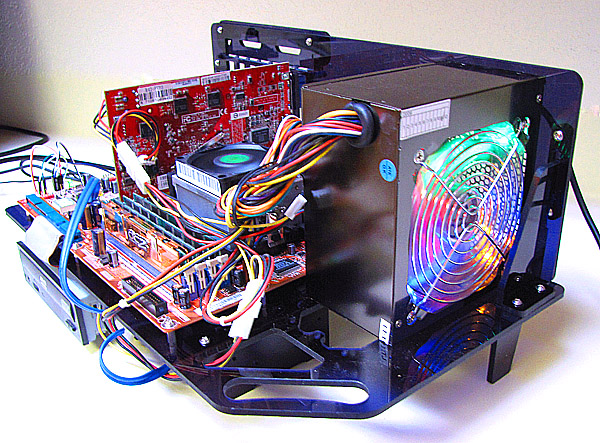
I’m a minimalist by nature, which is what attracted me to this “no-case” from My Open PC in the first place. I have often toyed with the idea of designing something similar, myself—just a couple of panels with the bare-minimum cutouts to meet the ATX specification. While, over the long run, I think there are good reasons to keep a PC’s guts inside a hard case, in the short term, an open fixture like this has a lot to recommend it, for instance as a test fixture for experimenting with different hardware configurations. I’ve built every desktop PC I’ve ever personally owned, and between that activity and the occasional component upgrade I seem to generate a fairly consistent trickle of surplus computer equipment. And every so often that trickle pools up to the point that I can cobble together an extra working PC. That kind of kit-bashing usually requires a lot of experimentation part-swapping, and that’s exactly where this kind of open fixture excels.


These are the two biggest parts in the box, the mainboard plate and the back panel. The DOMA Pro consists of 16 total pieces of this 3/16″ CNC-milled translucent “smoke” black acrylic sheet, a case electronics package, and a box of metal hardware. There’s also a small acrylic wrench (which I did not use) for tightening the hexagonal coupling nuts used throughout assembly, a detailed parts list, and a page of instructions with nice clear isometric line drawings.


The metal hardware is very thoughtfully packaged in a six-compartment translucent polypropylene organizer with six separate snapping, hinged lids. A printed label stuck to the backside of the organizer identifies each bit by the name used for it in the instruction sheet, and there are at least one or two extras of each flavor. Such attention to detail seems characteristic of the product and its manufacturer, though they do make a couple of mis-steps, as I’ll discuss below.


The case electronics consist of two soft momentary push-button switches for power and reset functions, and one red and one green LED to indicate hard drive activity and system power, respectively, all of which come pre-wired with labelled sockets for your motherboard pins.


The fixture has space to mount one 5.25″ drive (typically an optical drive) and one or two 3.5″ drives slung under the mainboard plate. Assembly begins by screwing small one-size-fits-all acrylic side panels to your drives, which then interlock with the mainboard plate, riding underneath it where the drive side panels double as supports for the front edge of the case.


The drive assemblies are locked in place by a pairs of small cams sliding on hexagonal coupling nuts secured to the mainboard plate. This trick—using cheap hex standoffs as bearing surfaces for moving parts—is one of a couple of examples of clever CNC-panel design the DOMA Pro includes. It’s repeated with only slight variation in the locking bar mechanism that secures the top corners of the PCI cards in place—much faster than screws, but more secure than just letting the cards sit loose in the slots.


Assembly to the stage shown here took me a leisurely hour, or thereabouts. I went on to add motherboard, video card, and power supply, and then to do a bunch of drive-swapping in the course of scratching together a Linux box for use with my garage CNC equipment. Then I transferred the working setup to a traditional hard case.


The only significant problem I had with the DOMA Pro, as it came from the manufacturer, was that it was wobblier than I like. Which is to say, wobblier than it had to be. Specifically, the bolted joints at the corners between mainboard and back panels were loose, which lead to a bit of racking along the short horizontal dimension. Without having actually asked the designers about it, I’d guess the sloppy fit at these joints is caused by badly-specified hardware. Whipping out the micrometer shows that the acrylic panels are very close to nominal 3/16″ thickness at 0.185″, while the coupling nuts that pass through them, which I bet are nominally 3/8″ (0.375″) are a bit long at 0.385″. I ended up shimming mine out with bits of tape between the two acrylic panels, and the problem went away.


The other small problem I had was with the female one-pin socket on the end of the positive leg of the system power LED. Specifically, it fell off after a single installation-removal cycle. Easily fixed, of course, but a bit annoying.


Overall, I really like this case both in theory and in practice. And considering its accessible price, it remains a great value in spite of the one or two small problems I had during assembly.